PAR Series
PAR Series – AC Dielectric Testers using Parallel Resonant Technology
in the ?
Features and Benefits
The PAR Series models are high voltage AC Dielectric Test Sets used for testing many types of utility substation apparatus, aerial lifts, cables, and other loads requiring AC voltage to perform Withstand/Proof testing and Diagnostic testing: Partial Discharge and Tan Delta/Power Factor testing. This model line provides a high power and high voltage AC output like conventional 50/60 Hz. test sets. However, the PAR Series is of unique design intended to test highly capacitive apparatus and cables. Its design tests these loads while minimizing the input power, size, weight, and cost of the supply. The PAR Series uses Resonant Technology, specifically: Variable Inductance Parallel Resonance.
Technology Overview
Resonance Technology is used to AC test highly capacitive electrical apparatus or power cable using 50/60 Hz. power frequency. The charging currents of these capacitive loads are typically very high, requiring AC hipots to be rated for hundreds of kVA in power. Resonant technology uses basic and long proven electrical principles for its design and operation to reduce the levels of power consumption needed, permitting high voltage AC testing to be performed more economically than otherwise possible. Using the PAR Series, the input current required of the supply is typically 10x – 30x less than if conventional fixed inductance power supplies were used. The HV transformer, or reactor, design includes a variably adjustable air gapped steel core to alter the Inductance of the system to compensate for the Capacitance of the load tested. The intention is to create a controlled resonance situation where L = C, leaving only the resistive elements of the load needing current/power from the test set.
Models & Specifications
The model ratings offered by HVI are designed to be optimal for factory or field testing motors and generators as well as substation apparatus like switchgear, bus ducts, arrestors or bushings, and shorter MV cable lengths. Other sizes are available on a custom basis. (HVI produces only Parallel Resonant, no Series.)
| Output | Input | ||||||
|---|---|---|---|---|---|---|---|
| Model | Voltage | kVA | Amps | Voltage | kVA | Amps | Freq. |
| PAR-1680FC5 | 0 – 16 kVac @ | 80 kVA | 5 A | 230 V @ | 10 kVA | 45 A | 50/60 Hz. |
| PAR-32/16160FC5 | 0 – 32 kVac @ | 160 kVA | 5 A | 230 V @ | 20 kVA | 90 A | 50/60 Hz. |
| 0 – 16 kVac @ | 160 kVA | 5 A | 230 V @ | 20 kVA | 90 A | 50/60 Hz. | |
| PAR-32250FC5 | 0 – 32 kVac @ | 250 kVA | 8 A | 230 V @ | 20 kVA | 90 A | 50/60 Hz. |
| PAR-50250FC5 | 0 – 50 kVac @ | 250 kVA | 5 A | 230 V @ | 20 kVA | 90 A | 50/60 Hz. |
| PAR-100100FC5 | 0 – 100 kVac @ | 100 kVA | 1 A | 230 V @ | 10 kVA | 45 A | 50/60 Hz. |
| Dimensions (in) | Weight lbs | Dimensions (cm) | Weight kg | |
|---|---|---|---|---|
| 10 KVA Input Models | ||||
| Controller | 21”w x 25.5”d x 31”h | 210 lbs. | 53w x 65d x 79h cm | 95 kg |
| HV Tank | 28”w x 28”d x 37”h | 800 lbs. | 71w x 71d x 94h cm | 364 kg |
| 20 KVA Input Models | ||||
| Controller | 22”w x 25.5”d x 47.5”h | 310 lbs. | 56w x 65d x 121h cm | 141 kg |
| HV Tank | 30”w x 30”d x 52”h | 1100 lbs. | 76w x 76d x 132h cm | 499 kg |
Resonant Operation
To calculate the test current: Amps = 𝟐𝝅𝒇𝑪𝑽 or A = ωCV ω (omega) = 2𝝅𝒇 f = frequency (Hz.) C = load capacitance (farads) V = test voltage (volts)
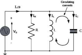
Parallel RLC Resonant Circuit
In Parallel Resonant circuits, resonance occurs when the Inductive Reactance (XL) of the variable inductor resonant set is “tuned” to match the Capacitive Reactance (Xc) of the load, in effect canceling out the capacitive nature of the load leaving only the resistive elements. The total circuit current is then “in-phase” with the supply voltage as the two equal and opposite reactive components cancel each other out.
Resistance = R, XL = ωL, XC = 1/ωC
ω = 2πƒ (ƒ = frequency)
ω for 50 Hz. = 314 ω for 60 Hz. = 377
Quality Factor “Q”
The Quality “Q” Factor is a measure of the level of power input reduction to the test set to deliver the power needed for a test. The Q, or quality, factor of a resonant circuit is a measure of the purity, or quality, of a resonant circuit. Q is the ratio of power stored (reactance) to power dissipated (resistance).
Q = Pstored / Pdissipated = I2X / I2R = X/R where X = Capacitive or Inductive reactance.
In a parallel resonant circuit, the power, or kVA, across the load is approximately Q times the total system input power. For example:
- A circuit with a Q of 20 would draw 1 kVAof input power from the mains forapproximately 20 kVA of reactive poweracross the load.
- A parallel resonant set, rated for 50 kVac@ 5 A output, tuned to the capacitivereactance of a bus duct or switchgearcould deliver 250 kVA of apparent powerto the load while drawing less than 10kVA of power from the utility mains.
- A generator stator winding, with a typicalQ of 10, would draw less than 11 kVAfrom the mains while 100 kVA of reactivepower is applied to the coils.
Controls: Manual or Automatic via Programmable Logic Controller
HVI offers a dual mode controller design. The PLC supplied can be user programmed to fully automate repetitive testing in automatic mode or perform simple hipot tests in manual mode. Test profiles for automatic mode can be preset at the factory or can be entered via the front panel touch screen control or a remote PC. Operation is easily modified using Ladder Logic Programming.
System Features
PLC Controller supplied Auto/Manual Output Mode selection Continuously adjustable motorized output voltage Programmable output Rate of Rise: 500 – 5000 volts/second Fixed primary current overload, factory set to 120% of current Adjustable secondary current overload: 10-110% of rating. “Zero Start” and External Interlock provision. Secondary connected volt and current meters
Features Include:
Automatic or Manual Mode 320 x 240 large color touch display Output voltage/current graphically display Complete graphical display at test end Test report generation Save and recall test profiles
User Settable Parameters
- Automatic or Manual Mode
- Voltage set point
- Over current set point
- Test Dwell Time
- Voltage Rate of Rise (10 – 100 sec)
Selecting an AC Test Set kVA Rating
The voltage rating of the instrument needed is known by the test specification or standard followed. The current rating required must be determined. Based on the capacitance of the load, use the following formula to calculate the load current:
Amps = ωCV, ω (omega) = 2
f = frequency (Hz.) C = load capacitance (farads) V = test voltage (volts)
To calculate the test current:
Amps = or A = ωCV
ω (omega) = 2
f = frequency (Hz.)
C = load capacitance (farads)
V = test voltage (volts)
Parallel RLC Resonant Circuit
In Parallel Resonant circuits, resonance occurs when the Inductive Reactance (XL) of the variable inductor resonant set is “tuned” to match the Capacitive Reactance (Xc) of the load, in effect canceling out the capacitive nature of the load leaving only the resistive elements. The total circuit current is then “in-phase” with the supply voltage as the two equal and opposite reactive components cancel each other out.
Resistance = R, XL = ωL, XC = 1/ωC
ω = 2πƒ (ƒ = frequency)
ω for 50 Hz. = 314 ω for 60 Hz. = 377
Quality Factor “Q”
The Quality “Q” Factor is a measure of the level of power input reduction to the test set to deliver the power needed for a test.
The Q, or quality, factor of a resonant circuit is a measure of the purity, or quality, of a resonant circuit. Q is the ratio of power stored (reactance) to power dissipated (resistance).
Q = Pstored / Pdissipated = I2X / I2R = X/R where X = Capacitive or Inductive reactance.
In a parallel resonant circuit, the power, or kVA, across the load is approximately Q times the total system input power. For example:
- A circuit with a Q of 20 would draw 1 kVA of input power from the mains for approximately 20 kVA of reactive power across the load.
- A parallel resonant set, rated for 50 kVac @ 5 A output, tuned to the capacitive reactance of a bus duct or switchgear could deliver 250 kVA of apparent power to the load while drawing less than 10 kVA of power from the utility mains.
- A generator stator winding, with a typical Q of 10, would draw less than 11 kVA from the mains while 100 kVA of reactive power is applied to the coils.